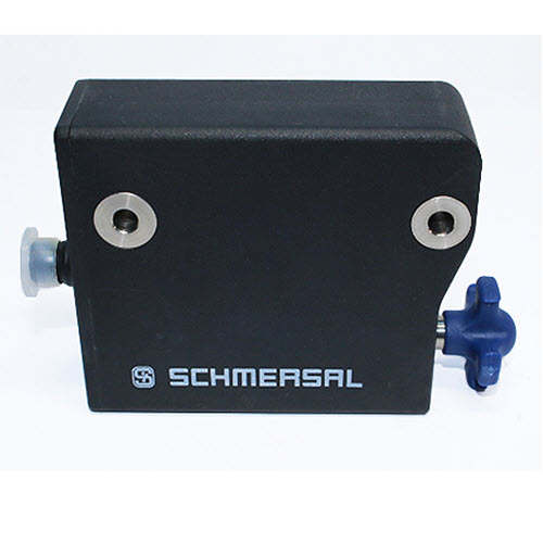
AZM300Z-I2-ST-1P2P-A SCHMERSAL 103001454 Solenoid interlocks
$0.00
Manufacturer
SCHMERSAL
Type of safety switch
bolting
Manufacturer series
AZM 300
Number of key entry slots
3
IP rating
IP69
Electrical connection
M12 8pin terminal
Body material
plastic
Colour
black
Mechanical durability
1000000 cycles
Operating temperature
0…60°C
Related items
101218025
Body dimensions
87.4×102.6×34.4mm
Force
1150N
Safety outputs
2
General data
Standards
EN ISO 13849-1
EN ISO 14119
EN IEC 60947-5-3
EN IEC 61508
Coding
Individual coding, multiple teaching
Coding level according to EN ISO 14119
High
Working principle
RFID
Frequency band RFID
125 kHz
Transmitter output RFID, maximum
-6 dB/m
Housing material
Glass-fibre, reinforced thermoplastic
Duration of risk, maximum
200 ms
Reaction time, switching off safety outputs via actuator, maximum
100 ms
Reaction time, switching off safety outputs via safety inputs, maximum
1.5 ms
Gross weight
550 g
General data – Features
Power to lock
Yes
Solenoid interlock monitored
Yes
Latching
Yes
Manual release
Yes
Short circuit detection
Yes
Cross-circuit detection
Yes
Series-wiring
Yes
Safety functions
Yes
Integral system diagnostics, status
Yes
Number of actuating directions
3
Number of fail-safe digital outputs
2
Safety classification
Vorschriften
EN ISO 13849-1
EN IEC 61508
Safety classification – Interlocking function
Performance Level, up to
e
Category
4
PFH value
5.20 x 10⁻¹⁰ /h
PFD value
4.50 x 10⁻⁵
Safety Integrity Level (SIL), suitable for applications in
3
Mission time
20 Year(s)
Safety classification – Guard locking function
Performance Level, up to
d
Category
2
PFH value
2.00 x 10⁻⁹ /h
PFD value
1.80 x 10⁻⁴
Safety Integrity Level (SIL), suitable for applications in
2
Mission time
20 Year(s)
Mechanical data
Mechanical life, minimum
1,000,000 Operations
Note (Mechanical life)
When using as door stop: ≥ 50.000 operations (door mass ≤ 5 kg and actuating speed ≤ 0.5 m/s)
Angular misalignment between solenoid interlock and actuator, maximum
2 °
Holding force FZh in accordance with EN ISO 14119
1,150 N
Holding force Fmax, maximum
1,500 N
Latching force, adjustable, position 1
25 N
Latching force, adjustable, position 2
50 N
Type of the fixing screws
2x M6
Tightening torque of the fixing screws, minimum
6 Nm
Tightening torque of the fixing screws, maximum
7 Nm
Mechanical data – Switching distances
Switch distance, typical
2 mm
Assured switching distance “ON” Sao
1 mm
Assured switching distance “OFF” Sar
20 mm
Note (switching distance)
All switching distances in accordance EN IEC 60947-5-3
Mechanical data – Connection technique
Length of sensor chain, maximum
200 m
Note (length of the sensor chain)
Cable length and cross-section change the voltage drop dependiing on the output current
Note (series-wiring)
Unlimited number of devices, oberserve external line fusing, max. 31 devices in case of serial diagnostic SD
Termination
Connector M12, 8-pole, A-coded
Mechanical data – Dimensions
Length of sensor
120 mm
Width of sensor
87.5 mm
Height of sensor
35 mm
Ambient conditions
Degree of protection
IP66
IP67
IP69
Ambient temperature
+0 … +60 °C
Storage and transport temperature
-10 … +90 °C
Relative humidity, maximum
93 %
Note (Relative humidity)
non-condensing
non-icing
Resistance to vibrations
10 … 150 Hz, amplitude 0.35 mm
Restistance to shock
30 g / 11 ms
Protection class
III
Permissible installation altitude above sea level, maximum
2,000 m
Ambient conditions – Insulation values
Rated insulation voltage Ui
32 VDC
Rated impulse withstand voltage Uimp
0.8 kV
Overvoltage category
III
Degree of pollution
3
Electrical data
Operating voltage
24 VDC -15 % / +10 % (stabilised PELV power supply)
No-load supply current I0, typical
100 mA
Current consumption with magnet ON, average
200 mA
Current consumption with magnet ON, peak
350 mA / 200 ms
Rated operating voltage
24 VDC
Operating current
800 mA
Required rated short-circuit current
100 A
External wire and device fuse rating
2 A gG
Time to readiness, maximum
5,000 ms
Switching frequency, maximum
0.5 Hz
Utilisation category DC-12
24 VDC / 0.05 A
Electrical fuse rating, maximum
2 A
Electrical data – Magnet control
Designation, Magnet control
IN
Switching thresholds
-3 V … 5 V (Low)
15 V … 30 V (High)
Current consumption at 24 V
10 mA
Magnet switch-on time
100 %
Test pulse duration, maximum
5 ms
Test pulse interval, minimum
40 ms
Classification ZVEI CB24I, Sink
C0
Classification ZVEI CB24I, Source
C1
C2
C3
Electrical data – Safety digital inputs
Designation, Safety inputs
X1 and X2
Switching thresholds
−3 V … 5 V (Low)
15 V … 30 V (High)
Current consumption at 24 V
5 mA
Test pulse duration, maximum
1 ms
Test pulse interval, minimum
100 ms
Classification ZVEI CB24I, Sink
C1
Classification ZVEI CB24I, Source
C1
C2
C3
Electrical data – Safety digital outputs
Designation, Safety outputs
Y1 and Y2
Design of control elements
short-circuit proof, p-type
Voltage drop Ud, maximum
2 V
Leakage current Ir, maximum
0.5 mA
Voltage, Utilisation category DC-12
24 VDC
Current, Utilisation category DC-12
0.25 A
Voltage, Utilisation category DC-13
24 VDC
Current, Utilisation category DC-13
0.25 A
Test pulse interval, typical
1000 ms
Test pulse duration, maximum
0.5 ms
Classification ZVEI CB24I, Source
C2
Classification ZVEI CB24I, Sink
C1
C2
Electrical data – Diagnostic outputs
Designation, Diagnostic outputs
OUT
Design of control elements
short-circuit proof, p-type
Voltage drop Ud, maximum
2 V
Voltage, Utilisation category DC-12
24 VDC
Current, Utilisation category DC-12
0.05 A
Voltage, Utilisation category DC-13
24 VDC
Current, Utilisation category DC-13
0.05 A
Status indication
Note (LED switching conditions display)
Operating condition: LED green
Error / functional defect: LED red
Supply voltage UB: LED green
Pin assignment
PIN 1
A1 Supply voltage UB
PIN 2
X1 Safety input 1
PIN 3
A2 GND
PIN 4
Y1 Safety output 1
PIN 5
OUT Diagnostic output
PIN 6
X2 Safety input 2
PIN 7
Y2 Safety output 2
PIN 8
IN Solenoid control
Scope of delivery
Scope of delivery
Actuator must be ordered separately.
Accessory
Recommendation (actuator)
AZ/AZM300-B1
Detalles
SI TE INTERESA ESTE COMPONENTE
Envíanos tus requeriemientos y nuestro equipo te dará una respuesta rápida.
ventas@mromasterpro.com
Directo desde tu teléfono móvil
Proporciona tus requeriemientos llenando la forma directamente.